The robot has to find a path across a wall. The robot simply moves forward, if it hits a wall moves backward, turn right, moves forward for short distance, turn left and moves forward again. The robot operates this loop until it find a path, i.e. a hole or a door, and then stops.
The robot finding s path
The robot is a first approach of more complex robots which can have many applications, the Electronic Engineering Laboratory has built a lots of different Mazemouse robots. The purposes of these robots are to find their way in an unknown labyrinth, there are famous micro-mouse competitions in England.
More information available at the following URL: http://www.ukc.ac.uk/electronics
The Kim3 robot built in 1994

Normally the robots are controlled by a microprocessor, the most current is the 68HC11. This is due to the fact that a robot has to operate complex tasks.
But for this project we will use VHDL, even if s not the easiest approach, to show that pure logic is able to control a sequential process efficiently.
For sequential real-time system we use a Finate State Machine representation which represent the different states of the machine and which variables create the transition from a machine to an other one.
The FSM of the robot
At the beginning the robot is in an Idle state and waits for the start button to be pushed. Then the first state is Forward_look, the robot moves forward until it finds a wall or s movement is done. If the movement is done, the robot goes back in the Idle state, but if the front sensors detect an obstacle, the robot state machine goes to the next state. The next states create a loop because the robot goes from a state to the next one when the movement is done, this continues until the movement is done in the Forward_look state, then the robot stop.
Each state has a condition on the start push button to stop the robot at any time.
As previously said an Altera device programmed in VHDL will control the robot.
For the movement we choose to use DC electrical motors, the same as the remote controlled cars, they are big enough to move the robot and carry the batteries.
An important part of the control of the robot is based on it's ability to evaluate the distance reached. The first approach was to use encoded optical wheels linked to the motors, but for mechanical reasons it was difficult to implement, moreover it's not accurate at all as far as the vibrations will create undesirable pulses and the distance will not be real.
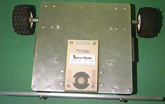
Another idea was to use a PC mouse. The advantages are that it is very accurate and it can avoid the effect of vibrations thanks to the two ways counting technique used, so it can detect if the robot is going either forward or backward.
A PC mouse is normally plugged into the serial port of a computer, in our case we can't use a serial link, we need to take the pulses directly inside the mouse. The pulses were TTL compatible, and so usable with the Altera device.
The mouse works with two power supplies +5V and -12V, so the robot has to provide both.
After a few tests using the 68HC11 board, the mouse reveals to be very accurate and the value obtained for the distance we want to use are around the value 1000, so we need to use at least 12 bits signed counters. In practice we used 16 bit counters, but we could change the size of those counters in the VHDL.
The mouse in place under the robot